Author: Dr. David Bernard, X-ray Consultant for the Electronics Industry (dbc@bernard.abel.co.uk)
This 2-part article has been commissioned by Excillum to celebrate the 125th anniversary of the discovery of X-rays on 8 November 1895. The first part reviews the history of X-rays and their use from then to now. The second looks at the history and recent developments in X-ray sources and show how their capabilities and use continues to grow and impact on our lives. Read part 1 here.
Part 2 – X-ray tubes
X-rays are created when electrons are fired at a high-accelerating voltage into a target element or alloy. Most elements, from atomic numbers 20 to 84, are, in principle, capable of generating X-rays. However, for practical reasons, a more limited set of materials is typically used to produce X-rays for today’s applications and Tungsten (Wolfram) is one of the most common. X-ray generation is achieved in two ways from the incoming accelerated electrons.
Firstly, they can interact with a bound electron of the target material and cause its ejection from the inner shell of the atom. Outer shell electrons then relax into this vacant energy level and release the energy difference as X-rays. These are known as the characteristic, or shell, X-rays and have specific wavelengths depending on the target material used. Characteristic X-rays were discovered by Charles Glover Barkla in 1909 and he won the Nobel Prize in Physics for his discovery in 1917.
Secondly, accelerated electrons can pass close to the much more massive nuclei of the target material. This interaction causes the electrons to slow and the reduction in energy through this slowing is given out as X-rays. These are known as the bremsstrahlung X-rays, or ‘braking radiation’ X-rays, from the German. Bremsstrahlung X-rays have a wide range of X-ray wavelengths, up to that created from the maximum accelerating voltage applied, owing to the variability in the braking interaction of the electrons with the nuclei.
The output from an X-ray tube, therefore, is a combination of the shell and bremsstrahlung X-rays and can be considered as a ‘white light’ source. Achieving the production of X-rays requires that these physical processes occur within a vacuum enclosure so that the electrons are not absorbed by the air before they strike the target material. The device that achieves this is usually referred to as an X-ray tube.
Early and sealed tubes
Electrons can be produced in three principle ways. These are photoemission (PE), thermionic emission (TE) and field emission (FE).
From the earliest history of X-rays, thermionic emission has been the easiest method to generate the electrons needed within an X-ray tube. Initially this was through the use of what we now call cold cathode, or electrical discharge, tubes, such as the Crookes tube. They were discovered in around 1870 and were even used by Röntgen himself. A cold cathode does not necessarily mean it operates at a low temperature! This is just the terminology used today to differentiate its operation from the later ‘hot’ cathode tubes invented by Coolidge in 1913 (see image 1). As in all future X-ray tube developments, the Coolidge tube allowed for improved X-ray quality and quantity for medical and other applications. The advances within the Coolidge tube meant that it operated at a much better level of vacuum and used a heated tungsten filament as the electron source. The improved vacuum ensured little, if any, remaining residual gas stayed within the vacuum enclosure and thereby prevented any X-ray production from its discharge at the expense of X-ray production at the target. By heating the cathode filament, the tube is able to emit electrons much more efficiently and the hotter the filament gets then the greater the emission of electrons. With more electrons available then more can strike the target and so provide a much brighter (more intense) X-ray source. Additionally, Coolidge tubes were much more stable and reliable compared to what went before. They also gave the user independent control over the achievable X-ray energy and the source intensity through, respectively, the setting of the applied accelerating voltage (kV) and the current (mA) or power (W)) through the filament.
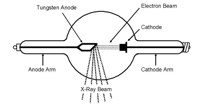
Image 1: Schematic of Coolidge hot cathode X-ray tube (Ref: W.D. Coolidge. The development of modern roentgen-ray generating apparatus. Am. J. Roentgenology. 24: 605-620. 1930.)
The descendants of the Coolidge tube are still used today. They are often called sealed, or closed, tubes, indicating that the vacuum is self-contained, and therefore maintained, within an enclosed glass, or other, vessel. In the early days, this was the best method to achieve the high level of vacuum necessary for long term, optimal X-ray production. Although still useful for many applications, including in the medical field, closed tubes have limitations on the quantity, or flux, of X-rays that they can provide at the highest image resolution and the image magnification that they can achieve. This occurs because focussing electrons onto a metal target generates heat and this has to be removed, else there is a danger of modifying, or damaging, the target. This was overcome to some extent by the development in the 1930s of a rotating anode within the vacuum enclosure (see images 2a and 2b). This permits fresh, and possibly cooled, areas of the target to be exposed to the incoming electrons, yet still be able to safely dissipate the heat produced.
Rotating anode tube
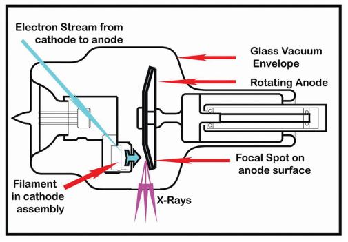
Image 2a: Schematic of rotating anode X-ray tube. (Ref. https://thoracickey.com/ cineangiographic-imaging-radiation-safety-and-contrast-agents/; www.thoracickey.com)
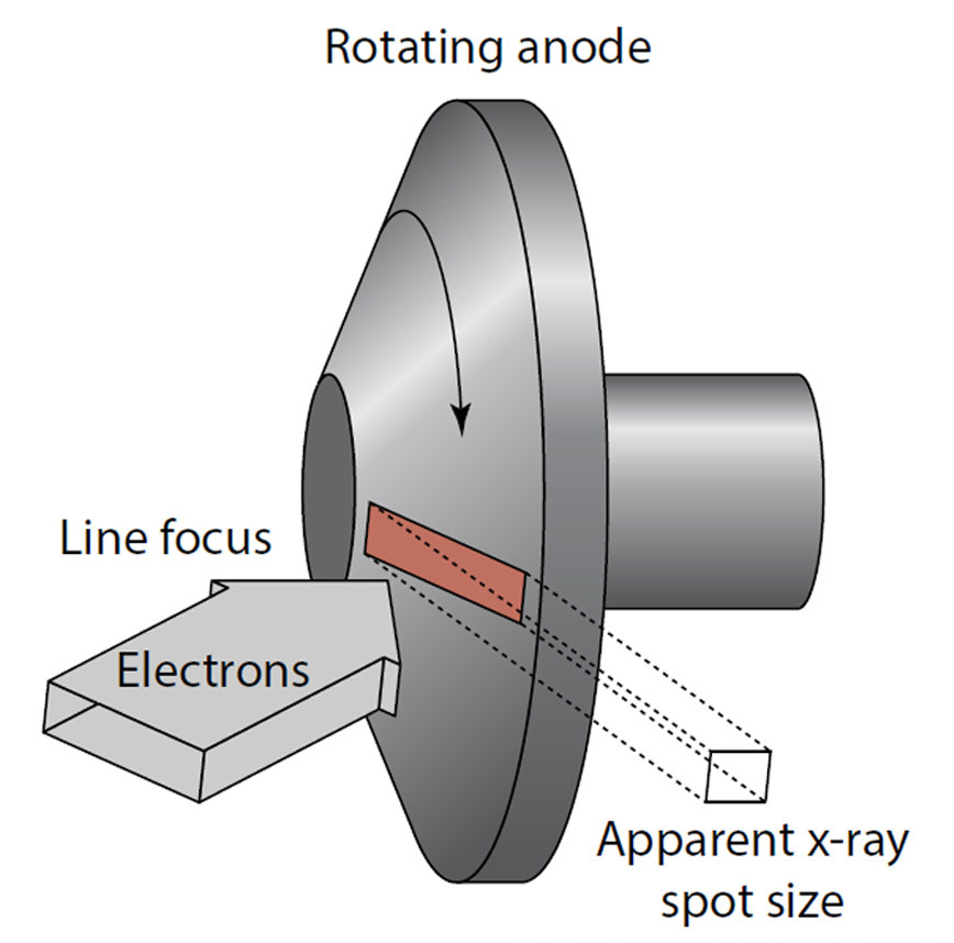
Image 2b: Schematic of X-ray generation from a rotating anode and the relative size of the focal spot it generates. (Ref. Image courtesy of Excillum AB)
The sealed tube limitations of magnification and resolution were an issue for those who wanted to undertake X-ray microscopy. The resolution of any light source, optical or X-ray, is ultimately determined by how small the point of origin of that light is. In X-ray tubes, this point of origin is called the focal spot and is the area of X-ray emission on the target. For sealed X-ray tubes the focal spot diameter will be ~ 8-10 microns, or greater, and often more for rotating anode variants (see image 2b). This resolution is an order of magnitude poorer than for an optical system and is why, therefore, X-ray images are not as sharp as optical ones.
To improve the resolution of the sealed tube it would be necessary to focus the incoming accelerating electrons into an even smaller impact area. However, this would substantially increase the energy density being put into the metal target at the focal spot and that may well overwhelm the available heat dissipating capabilities of the tube and/or modify/damage/burn-through the target surface. If this were to happen then the whole tube could have to be expensively replaced and so, therefore, limits are applied on the resolution performance sealed tubes can be allowed to safely achieve.
Open tubes
Improved X-ray tube resolution was achievable from the 1950s onwards. This was through the availability and performance of higher quality vacuum pumps which could create the same high level of vacuum that could only previously be achieved within a sealed unit, but could do so locally, and in minutes, when needed. Therefore, this led to new X-ray tube designs that could operate the filament cathode and the target anode at much higher levels of performance by knowing that replacement filaments and targets could be installed, when required, and return the tube to its optimum performance in a short time. Such X-ray tubes are called open, or demountable, tubes and provide higher resolutions (focal spot sizes ~ 1-2 microns, or less) at reasonable flux, allowing, for example, quick and better X-ray image generation. It should be noted that there is no internationally agreed standard for measuring the resolution of open X-ray tubes and so the terms ‘nano-focus’ and ‘micro-focus’ are often used interchangeably to describe their performance.
The resolution improvement in open X-ray tubes was coupled with a change of target type to substantially increase the geometric magnification that they could achieve. The X-rays created within a tube have to exit the tube enclosure! Sealed tubes use what are called reflective targets, which means that for practical reasons the focal spot has to be at least 5-20 mm, or more, away from the nearest point of exit from the tube (see images 1 & 3). Part 1 of this article showed that the geometric magnification of an X-ray microscope is determined by the proximity of the sample to the focal spot. Therefore, a closed tube has in-built limits on the level of magnification it can provide. In comparison, open tubes allowed the development of the transmission target (see images 3 & 4) that enables the focal spot to be much closer to the exterior of the tube. The target is thin enough to generate X-rays but still able to transmit them through its own thickness to the outside world without total self-absorption. This thin metal target is usually deposited on a diamond, beryllium or aluminium substrate, which are transparent to the X-rays, yet still provide a seal for the vacuum enclosure. As a result, a transmission target can allow a sample to be placed 0.5mm, or less, from the focal spot of an open tube, substantially increasing the available geometric magnification. A simple schematic of this is shown in image 3.
In recent years, the availability and use of diamond substrates under the transmissive target material has also allowed more heat to be effectively dissipated at the focal spot thereby enabling increased X-ray flux at these ‘sub-micron’ resolution levels. In addition, the total target thickness can be smaller than if other substrate materials are used. These types of open tubes are most commonly used in the electronics industry for imaging the continually shrinking electronic components and their joints.
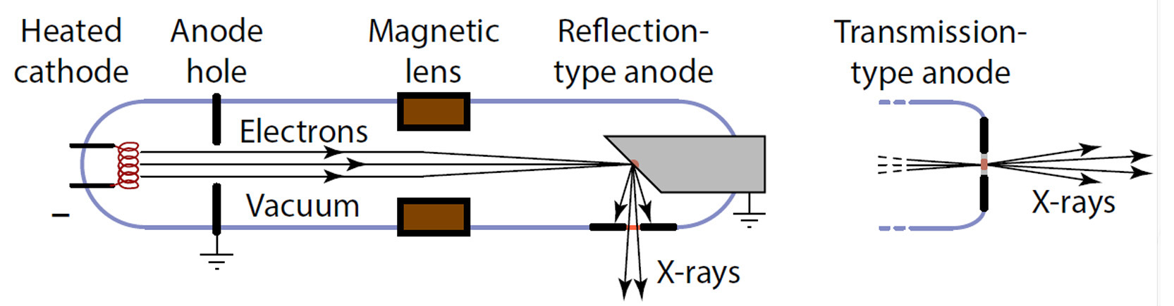
Image 3: Schematic of transmissive and reflective target types in X-ray tubes and the differences in their focal spot to tube exit (window) distance. (Ref. Image courtesy of Excillum AB). See also D. Bernard articles, https://tinyurl.com/y5ke9h25 & https://tinyurl.com/yy6cj9pw from www.circuitsassembly.com)
Synchrotron source
Outside of X-ray tubes, the other major development in X-ray sources came from the greater availability to researchers of the synchrotron ring in the 1970s. From a principle discovered in 1944 and first shown in 1946, synchrotron radiation is created from a type of circular particle accelerator that accelerates electrons through sequences of magnets until they reach relativistic speeds. Within this environment, these fast-moving electrons produce very intense light, predominantly in the X-ray region, and the output, through so called beam lines positioned around the ring, is millions of times brighter than that produced from a conventional X-ray tube and 10 billion times brighter than the sun. With such available brightness it is possible to monochromate the output to specific desired wavelengths yet still have sufficient flux for experimentation, something that cannot be achieved with a traditional X-ray tube. However, even the very smallest synchrotrons have a diameter of many 10s of metres plus a remarkably high cost to build and run, so making their output only practically available to a select few!
LaB6 & MetalJet tubes
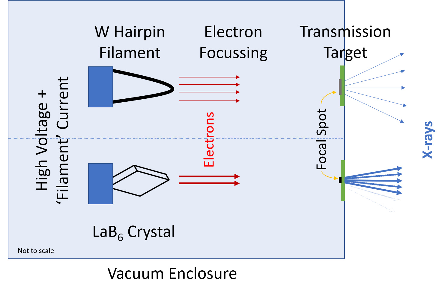
Image 4: Schematic of a comparison of open, transmissive-target X-ray tubes using either a Tungsten (W) hairpin filament or LaB6 crystal for electron generation and the relative effects these have on focal spot size and X-ray emission (flux). Emission is actually from almost 180° from the target exit surface but ray diagram is simplified for clarity.
If a synchrotron is not available to all then there have been some new developments in X-ray tubes in the 21st century to push and extend the X-ray output for resolution and flux beyond the historical limits of open tubes. This has been driven by applying the same approaches used to improve electron microscopes over the last 30 years, as they, too, have also needed smaller electron spots producing more flux. In particular, over the last 15 years, LaB6 (Lanthanum Hexaborate, or ‘Lab Six’ as it is commonly known) has started to be used for electron generation in place of the traditional tungsten ‘hairpin’ wire for the hot cathode. LaB6 is crystalline and can therefore be mounted as a sharp crystal point as the electron emission source within the tube compared with a minimum bend radius for a hairpin filament (see image 4). LaB6 also has greater electron emissivity than tungsten wire. Therefore, by making a smaller point of origin for the excitation electrons, and generating more of them than before, it means the electrons can be focussed more easily and tightly onto the target. This creates a smaller focal spot of X-ray emission so giving enhanced imaging resolution as well as a brighter source (see image 4).
It should be noted that there have also been some recent developments in using field emission for electron generation in place of thermionic emission. At present, however, these are specialised, and expensive, approaches compared to the other commonly available tube types mentioned.
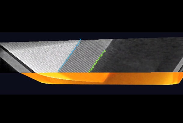
More recently, a new type of metal-jet X-ray tube has been available commercially that replaces the solid target with a jet of liquid metal. The advantage of this approach is that the maximum electron-beam power density can be significantly increased whilst still maintaining a small focal spot and yet remain within acceptable thermal limits (see image 5 and compare this to image 2b for a rotating anode configuration). Therefore, greater X-ray flux (higher brightness) is produced at enhanced resolution but there is no degradation of the target as it is being continually ‘refreshed’.
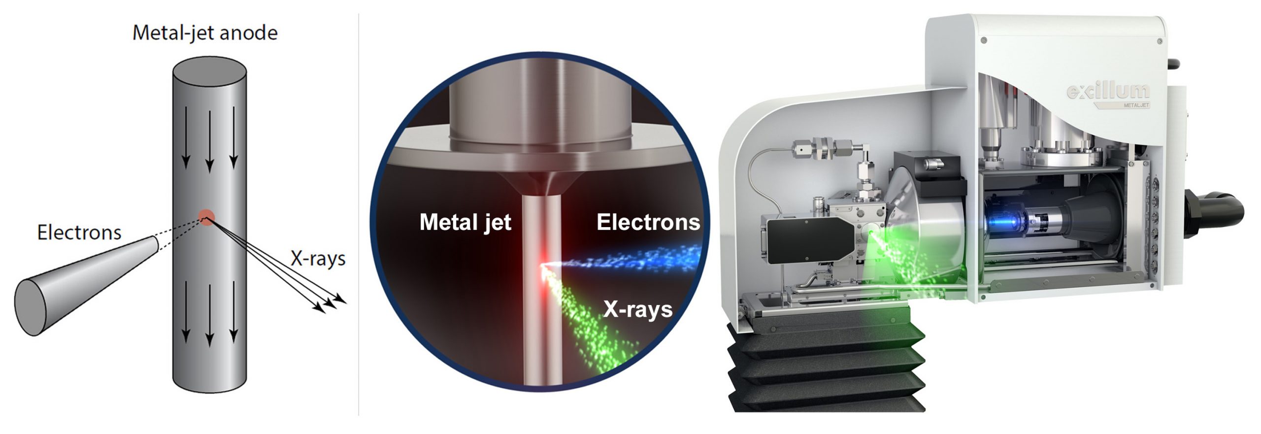
Image 5: Image of MetalJet X-ray tube with magnified diagrams of X-ray generation from a continuously recycled jet of metal alloy (image courtesy of Excillum AB).
From the time of Röntgen’s first glimpse of these ‘unknown’ rays in 1895, and which still continues to this day, great efforts have been made to improve the power, quality, quantity and resolution that can be produced by X-ray sources. This has enabled X-rays to be used for a multitude of previously unavailable practical applications in the analytical, medical, industrial, safety and security fields which so thoroughly improve and enrich our lives. So, who knows what future X-ray sources will bring?
Published: November 8, 2020